 XCP - Signal Config Filter Editor
This chapter will break down the usage of the XCP - Signal Config Filter Editor (SCFE).
After reading this article, you should have the knowledge:
- about the general usage of the SCFE.
- how to open the SCFE.
- how to create your own map files.
- how to create an outputpin with an array struct.
General usage
In general an ECU is described with an A2L file which includes all signals, parameters, DAQ events and much more.
The SCFE window is used to select signals and parameters from an A2L file and map them to the created pins for the
- XCP Encode Filter
- XCP Decode Filter.
Open the SCFE window
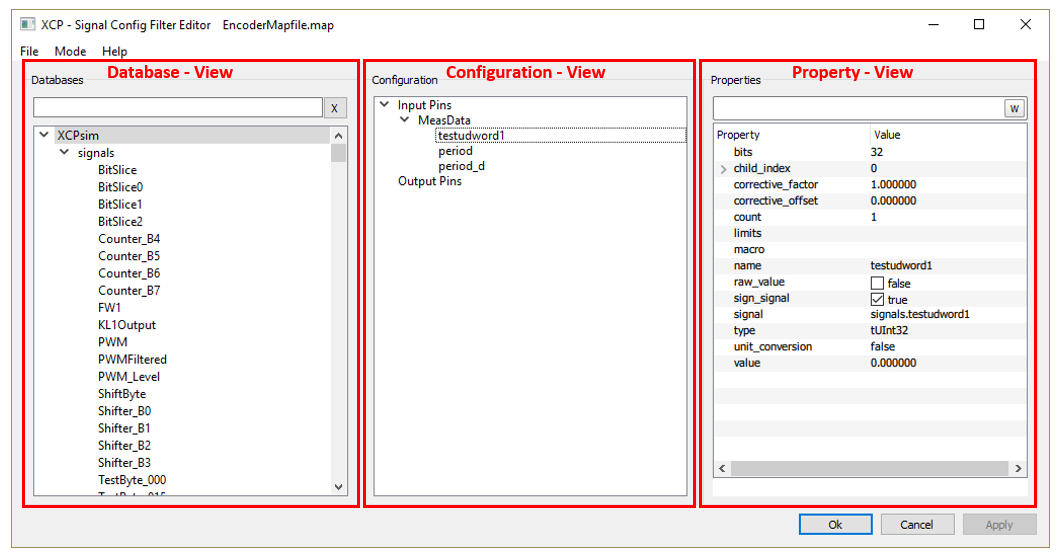
You have to open the context menu of the En-/Decode-Filter and choose 'Signal Config Filter Editor'. The dialog like the one you can see below will be displayed. If you have set the MapFilename property of the En-/Decode-Filter, the SCFE will show previously configured pins within the 'Configuration' view of the SCFE. Otherwise you won't see any pins or databases.
Create a new map file
To create a new map file for your filter, go into the SCFE and:
- Create a new configuration by choosing 'File' --> 'New Config' --> 'New Config'
- Add the A2L file corresponding to your ECU, by using the menu point 'File' --> 'Add Database ...'
- After the selected file is parsed, you will see all signals and parameters of your A2L file in the 'Database' view
- Safety first, save your config
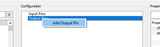
- Within the 'Configuration' view you can add pins to your configuration by open the context menu and clicking 'Add Output Pin' or 'Add Input Pin'
- Now it's time to configure the added pins. If a pin is selected, you can see its properties in the 'Properties' view.
It's important to edit the properties to enable the full functionality of the XCP communication:
Property Value Description cycletime Milliseconds Old behaviour: Cyclic transmission of a buffer. Default -1.
Note: this variable will not effect anything and will be disabled in the next releases.daq_event cString Defines the DAQ event channel daq_prescaler tUInt32 Transmission rate prescaler (=>1) name cString Pin name polling_interval tUInt32 Defines the polling interval
- After naming and configuring the pin you can drag and drop one or more signals from the 'Database' view to your new pin.
So the configruation could look like this:
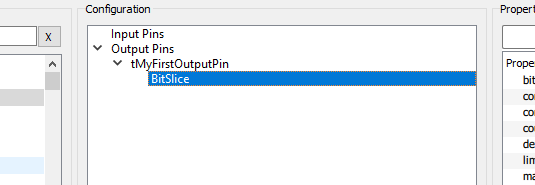
-
Like before, you have to configure your used signals/parameters via the 'Properties' view:
Property Type Description bits tUInt For bit field elements child_index tUInt32 Used as Structindex corrective_factor tFloat64 Additional factor corrective_offset tFloat64 Additional offset count tInt For array like signals, this specifies the dimension limits tInt Can be used to override the property setting for global limit handling macro cString Name of a macro that should be executed to fill the structure element
Note: this variable will not effect anything, but will be enabled in one of the next releases.name cString Name of the structure element raw_value tBool Switch if a raw value is used sign_signal cString Note: The sign_signal attribute of an element node is only within the ADTF_DeviceToolbox necessary.
Leave this proberty always empty, otherwise it is not possible to init your session.signal cString The exact notation of the SignalName as in the corresponding A2L file type tElementDataType Data type of the structure element unit_conversion tBool For read-in "unit_conversion" value cVariant Default value of the signal -
After you have completed the configuration step save the mapping by clicking the 'OK'-Button.
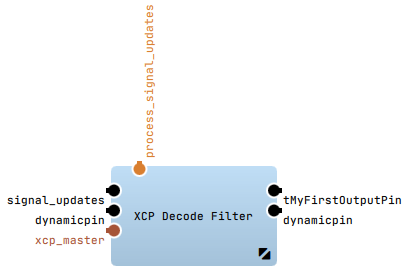
The currently opend map file will be used by the selected filter, which includes now your new configured pin.
Create an outputpin with an array struct
Using array structs for a big number of signals can help you safe configuration time and big mapfiles. You can use this functionality for signals with approximately the same signal names. The signal names can for example differ in a rising number at the end:
Counter_B0
Counter_B1
Counter_B2
Counter_B3- Add a new pin to your configuration.
- Configure the pin properties (daq_event, daq_prescaler or polling_interval).
-
You can add a struct to the pin by opening the context menu of the pin, clicking 'Add Struct...' and assign a name.
These struct objects can configured by following properties:
Property Type Description array_format cString printf format specifier for the array index. array_index_name cString A name that can be used to a placeholder for the array index in the element signal name (SignalName.Signal$array_index_name$). array_start_index tInt32 Start index of the array. array_stop_index tInt32 End index of the array. child_index tInt32 Used as Structindex. name cString Name of the Struct. pack tInt32 Memory packing of member elements. The default is 8. -
To add the four counter signals to the created struct, we have to set the properties:
array_format: %darray_index_name: idxarray_start_index: 0array_stop_index: 3name: Counter_Signals
<struct name="Counter_Signals" array="idx=0:3" array_format="%d"> -
Now, you can add one of the array signals by drag and drop from the database to the struct object.
Choose a generic name for the name property and replace the number of the signal property with the befor defined
array_index_name:name: Countersignal: signal.Counter_B$idx$
<struct name="Counter_Signals" array="idx=0:3" array_format="%d"> <assignment> <to>Counter</to> <from>signals.Counter_B$idx$</from> <type>tUInt8</type> </assignment> -
The Codec will now observe all incoming / outgoing signals regarding the configured struct and pack them together.
You can inspect the correct behaviour, by connecting a struct output pin to a Qt5 Media Description Display:
An array struct displayed in the Qt5 Media Description Display
Summary
We would like to roundup the article by explaining further SCFE functionalities.
The 'File' - menu
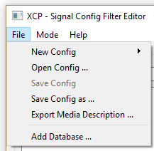 With the help of the file menu Configuration files and database files are handled.
The following menu points are available:
New Config: A new and empty map file will be generated. The 'Configuration' view will be empty.Open Config...: An existing map file can be opened. The content of the file will be displayed in the 'Configuration' view.Save Config: The current content of the 'Configuration' view will be saved to the currently loaded map file.Save Config as...: The current content of the 'Configuration' view will be saved in a new map file.Export Media Description...: With the help of this menu entry you can create a media description file for the current configuration.Add Database: An existing database file (e.g. *.a2l) has to be selected. The content of the file will be added to the 'Database' view as a new node.
The 'Mode' menu
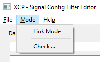 The 'Mode' menu offers additional operations that can be executed. The following menu entries are available:
-
Link Mode: The link mode can be (de-)activated. With activated link mode it is possible to relink existing structure elements in the configuration tree to another database signal. If the link mode is activated the text "Link Mode is active!" is shown in the statusbar. -
Check...: The current configuration will be checked. If an error is detected a message box is shown.