![]()
 Signal Config Filter Editor (SCFE)
This chapter will break down the usage of the SCFE.
After reading this article, you should have the knowledge:
- about the general usage of the SCFE.
- how to open the SCFE.
- how to create your own map files.
General usage
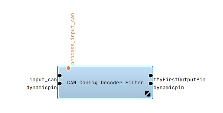
The SCFE dialog is used to select signals and parameters from a bus database file and map them to the created pins for the
- (Deprecated) CAN DBC Config Decoder Filter
- (Deprecated) CAN DBC Config Encoder Filter
- CAN FD DBC Config Decoder Filter
- CAN FD DBC Config Encoder Filter
- FlexRay Fibex Config Decoder Filter
- FlexRay Fibex Config Encoder Filter
So it is possible to configure the Encoder or Decoder Filter with the signals and parameters you need. For example you want to decode the velocity value of your car (which is measured by your connected engine control unit). So you have to select the velocity signal from loaded bus database(s) and create a output pin with this signal.
Open the SCFE window
You have to open the context menu of the En-/Decode-Filter and choose :
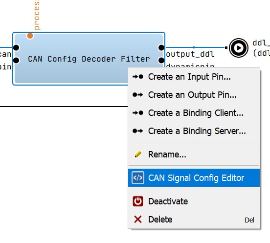
The dialog like the one you can see below will be displayed:
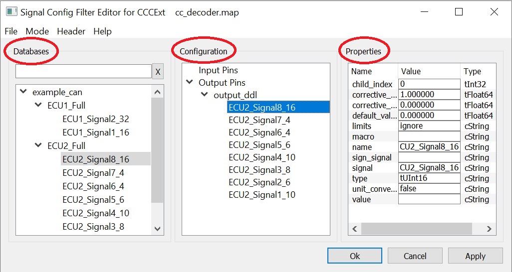
If you have set the MapFilename property of the En-/Decode-Filter, the SCFE load the configuration file and show the configured pins within the Configuration view. Otherwise you will get an empty configuration.
Create a new map file(CAN Config Decoder Filter)
To create a new map file for your filter, go into the SCFE and:
- Create a new configuration by choosing --> -->
- Add the database file according to your bus network, by using the menu point -->
- After the selected file is parsed, you will see all signals and parameters of your database file in the Databases view
- Safety first, save your configuration
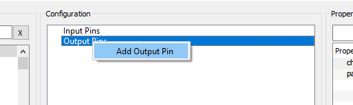
Within the Configuration view you can add pins to your configuration by open the context menu and clicking or :
- Now it's time to configure the added pins. If a pin is selected, you can see its properties in the Properties view.
It's important to edit the properties to enable the full functionality of the CAN communication:
Property Type Description channel tInt32 The channel on which the referenced messages and signals are available. channelmask cString Through the channel mask a range of possible channels can be specified. Each bit in this 32bit integer corresponds to a channel number. cycletime tInt32 Cyclic transmission of the buffer. Default -1. delay tInt32 A fixed delay that will be substracted from the buffer timestamp. name cString Pin Name pack tInt32 Memory packing in the buffer. The default is 8. timestamp cString Specifies when and how the time stamp is set for the decoded data: $FIRST$: time stamp of the first valid message in the cycle for this buffer $LAST$: time stamp of the last message in the cycle before the data of this buffer is sent. $MEAN$: average value of the $FIRST$ and $LAST$ time stamp MessageName: time stamp of the corresponding message is used if this is received (otherwise 0) After naming and configuring the pin you can drag and drop one or more signals from the Databases view to your new pin.
So the configuration could look like this: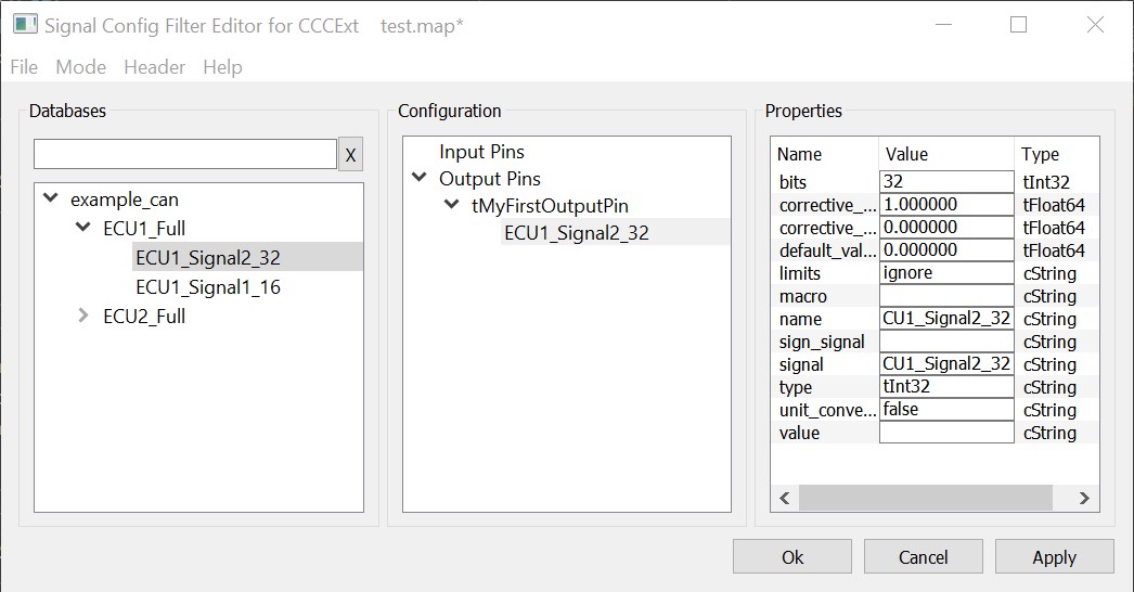
-
Like before, you have to configure your used signals/parameters via the Properties view:
Property Type Description bits tInt32 Signal bit length corrective_factor tFloat64 Additional computation factor corrective_offset tFloat64 Additional computation offset default_value tFloat64 Default value from database or configuration file limits cString Can be used to override the property setting for global limit handling macro cString Name of a macro that should be executed to fill the structure element
Note: Currently property has no effect, but will be enabled in one of the next releases.name cString Name of the structure element sign_signal cString Reference a seperate sign signal signal cString The exact notation of the SignalName as in the corresponding database file type cString Data type of the structure element unit_conversion cString For read-in "unit_conversion" value cString Set constant signal value -
After you have completed the configuration step, save the mapping by clicking .
The currently opened map file will be used by the selected filter, which now contains your new configured pin(s).
Property Description
| Property | Value | Optional | Description |
|---|---|---|---|
| channel | [0..16] | No, either channel or channelmask must be defined. | The channel on which the referenced messages and signals are available. |
| channelmask | hexadecimal | No, either channel or channelmask must be defined. | Through the channel mask a range of possible channels can be specified. Each bit in this 32bit integer corresponds to a channel number. |
| delay | milliseconds | yes | A fixed delay that will be substracted from the buffer timestamp. |
| pack | 1,2,4,8,16 | yes | Memory packing in the buffer. The default is 8. |
| timestamp | $FIRST$ $LAST$ $MEAN$ MessageName |
yes | Specifies when and how the time stamp is set for the decoded data: $FIRST$: time stamp of the first valid message in the cycle for this buffer $LAST$: time stamp of the last message in the cycle before the data of this buffer is sent. $MEAN$: average value of the $FIRST$ and $LAST$ time stamp MessageName: time stamp of the corresponding message is used if this is received (otherwise 0) |
| clear_after_transmit | bool | yes | Clear the buffer to 0 after transmitting. |
| cycletime | milliseconds | InputPin Only | Cyclic transmission of the buffer. Default -1. |
| Property | Value | Optional | Description |
|---|---|---|---|
| pack | 1,2,4,8,16 | yes | Memory packing in the buffer. The default is 8. |
| array_index_name | string | yes | A name that can be used to a placeholder for the array index in the elemnts’ signal name (MessageName.Signal$array_index_name$). |
| array_start_index | integer | yes | Start index of the array. |
| array_stop_index | integer | yes | End index of the array. |
| array_format | format specifier | yes | printf format specifier for the array index. |
The struct node defines a specific C-structure, whose elements can be filled with decoded signals, macros
or just nothing. A buffer node can contain multiple structs with different attributes (array, pack, etc.). When
creating the structures, special care must be taken that the "pack" specification
matches the #pragma pack (see Microsoft Visual Studio help) of the C-structure so that the alignment of the individual structure
elements fits! By default in Visual Studio, a #pragma pack(8) is set.
double value. GCC uses
a 4 byte alignment for all 64 bit types. For #pragma pack-values larger than 1, this can
lead to a different memory layout of the structure!
| Property | Value | Optional | Description |
|---|---|---|---|
| type | ADTF data type | no | Data type of the structure element. Valid types: tBool, tInt8, tUInt8, tInt16, tUInt16, tInt32, tUInt32, tInt64, tUInt64, tInt, tUInt, tFloat64, tFloat32 |
| signal | Message.Signal | yes, when macro is used | "MessageName.SignalName" in the exact notation as in the corresponding database file. |
| corrective_factor | float | yes | Factor to apply to the signal before the buffer is transmitted. |
| corrective_offset | float | yes | Offset to apply to the signal before the buffer is transmitted. |
| unit_conversion | bool | yes | Apply the unit conversion described in the database file. |
| sign_signal | SignalName | yes | Reference a separate sign signal. |
| limits | ignore clip warn |
yes | Select a limit handling policy. With this you can clip a signal to the min/max values specified in the database file or warn via log message when the limits are exceeded. |
| Property | Value | Optional | Description |
|---|---|---|---|
| timeout | milliseconds | yes | Triggers the buffer after the specified time (depends on the Stream Time) if the required signals have not been received entirely. If all signals were received before the timeout, the buffer is transmitted and the timeout will reset. |
| start_msg | MessageName | yes | The name of the message that triggers a new decoding cycle. All other received messages which are configured in the buffer will be ignored until this message was received. It is possible to use only the message as trigger (without valid checking see below). The start message has to be received at the same channel as configured in the buffer. |
| start_valid_signal | SignalName | yes | Used in combination with start_msg to select a signal in the message that is used as a source for a value comparison. |
| start_valid_value | NumericValue | yes | The value which the start_valid_signal will be compared against. |
| start_valid_operation | [==,!=,>=,<=,>,<] | yes | The operation used in the comparison. |
| stop_msg | MessageName | yes | The name of the message that stops the current decoding cycle. After receiving the message, a new sample will be transmitted. If there is configured a start_msg, all other received messages which are configured in the buffer will be ignored until the start_msg was received. It is possible to use only the message as trigger (without valid checking see below). The stop message has to be received at the same channel as configured in the buffer. The value should have the following structure: ECUName.PDUChannelValue.PDUName |
| stop_valid_signal | SignalName | yes | Used in combination with stop_msg to select a signal in the message that is used as a source for a value comparison. |
| stop_valid_value | NumericValue | yes | The value which the stop_valid_signal will be compared against. |
| stop_valid_operation | [==,!=,>=,<=,>,<] | yes | The operation used in the comparison. |
The optional trigger specifies when a decoding cycle begins and when it ends. If no such node exists, all appropriate messages are decoded and, if all messages required for the buffer were received, the sample is sent. During this step multiplexed signals are treated just as signals from different messages, i.e. all needed multiplexes of a message must have been received to trigger a transmit. By setting the stop_valid_signal to the multiplexor it is possible to trigger the buffer transmission on specific multiplexes. The stop trigger can be composed of a stop message (with an optional valid condition) and a timeout.
Summary
We would like to roundup the article by explaining further SCFE functionalities.
The File - menu
With the help of the - menu, configuration and database files are handled. The following menu points are available:
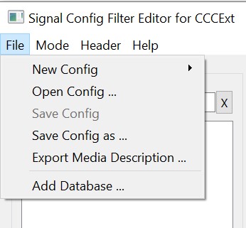
- : A new and empty map file will be generated. The Configuration view will be empty.
- : An existing map file can be opened. The content of the file will be displayed in the Configuration view.
- : The current content of the Configuration view will be saved to the currently loaded map file.
- : The current content of the Configuration view will be saved in a new map file.
- : With the help of this menu entry you can create a media description file for the current configuration.
- : An existing database file (e.g. *.dbc, *.xml, ...) has to be selected. The content of the file will be added to the Databases view as a new node.
The Mode - menu
The - menu offers additional operations that can be executed. The following menu entries are available:
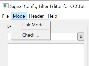
- : The link mode can be (de-)activated. With activated link mode it is possible to relink existing structure elements in the configuration tree to another database signal. If the link mode is activated the text "Link Mode is active!" is shown in the statusbar.
- : The current configuration will be checked. If an error is detected a message box is shown.