The Calibration Toolbox Components
Within this part we will explain the usage of the different components of the toolbox.Filters
- XCP Master Filter
- XCP Decode Filter
- XCP Encode Filter
- XCP Emulator Filter
- XCP On CAN Filter
- XCP On CAN FD Filter
- XCP On FlexRay Filter
- Qt5 XCP Master GUI Filter Plugin (BETA)
Streaming services
Filters
The XCP Master Filter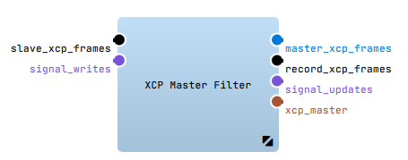
Introduction
The "XCP Master" - Filter connects the BUS devices (e.g. "XCP on CAN") in the streaming graph with the "XCP-En/Decode" - filters in the filter graph. The "XCP Master" - Filter provides the functionality to read from and write to XCP frames. In order to receive only a sub set of the available XCP values it is necessary to add a Binding Proxy between the "XCP Master" - Filter and the XCP De-/Encode Filter.
Configuration
The most important property of the "XCP Master" - Filter is the A2L or Xml Filename property where you should specify the A2L file that corresponds to the ECU that should be handled.
Keep in mind that the "XCP Master" - Filter requires to be connected to one of the XCP Transport Filters/Sinks or Sources (CAN, Ethernet, FlexRay) in order to communicate with the slave ECU.
For further information about the configuration options please refer to XCP Master Filter Plugin.
Jump to topThe XCP Decode Filter
Introduction
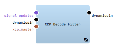 The "XCP Decode" - Filter can be used to read out signal values of electronic control units.
These values can be transformed from XCP frames into data structures common to ADTF (mediadescription)
that are transmitted over the configured output pins.
XCP allows two different modes for reading data from the ECUs memory:
The "XCP Decode" - Filter can be used to read out signal values of electronic control units.
These values can be transformed from XCP frames into data structures common to ADTF (mediadescription)
that are transmitted over the configured output pins.
XCP allows two different modes for reading data from the ECUs memory:
- DAQ: The "XCP Master" - Filter tells the ECU to continuously send a configured set of data at specific cyclic events.
- Polling: The "XCP Master" - Filter continuously polls the memory of the ECU with UPLOAD commands.
Configuration
The property MapFilename specifies a configuration file which defines, what signals are acquired and/or written and how the data structures are made up
that are sent over the filters output pins. For creating such a configuration file please see the Signal Config Filter Editor chapter.
For further information about the configuration options please refer to XCP Decode Filter Plugin.
Jump to topThe XCP Encode Filter
Introduction
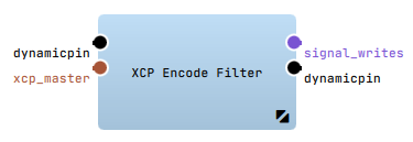 The "XCP Encode" - Filter can be used to change signal values of the connected electronic control unit.
The generated DDL values will be transformed into XCP frames and transmitted via your BUS filter to the ECU.
The "XCP Encode" - Filter can be used to change signal values of the connected electronic control unit.
The generated DDL values will be transformed into XCP frames and transmitted via your BUS filter to the ECU.
XCP allows two different modes for writing data to the ECUs memory:
- STIM: The XCP Master continuously sends a configured set of data to the ECU.
- Direct: The XCP Master continuously writes to the memory of the ECU with DOWNLOAD commands.
Configuration
The property MapFilename specifies a configuration file which defines what signals are acquired and/or written and how the data structures are made up
that are sent over the filters output pins. For creating such a configuration file please see the Signal Config Filter Editor chapter.
For further information about the configuration options please refer to XCP Encode Filter Plugin.
Jump to topThe XCP Emulator Filter
Introduction
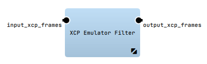 The XCP Emulation Filter allows you to simulate any given ECU for which an A2L description file is available.
Configuration
To do so you specify the A2L file within the A2L or Xml Filename property and connect the filter with the
XCP Transport Filter/Sink or Source (CAN, Ethernet, etc.) of your liking.
Please make sure that you enable the Slave Mode property of your transport filter.
The behaviour of the emulated ECU is described via a mandatory configuration file that specifies several so called ECU Processors.
ECU Processors are plugins that can write to and read from ECU memory locations and react upon trigger events in the ECU.
Please see following section for details.
For further information about the configuration options please refer to XCP Emulator Filter Plugin.
ECU Processor Configuration
The XML configuration file format is best described with the help of the following example:
  <?xml version="1.0" encoding="utf-8" standalone="no"?>
  <settings>
    <ecu_processors>
        <processor oid="adtf.ecu_processor.cyclic" event_name="100ms" interval="100000" />
        <processor oid="adtf.ecu_processor.constants" count="2" signal0="byteConstant1" value0="123" signal1="byteConstant2" value1="321" />
        <processor oid="adtf.ecu_processor.counter" signal_name="wordCounter" interval="50000" />
        <processor oid="adtf.ecu_processor.adtf_signal" signal_name="sawtooth" adtf_signal_name="Demo_Sawtooth_Provider/Demo Sawtooth Signal 0" />
    </ecu_processors>
  </settings>
You can specify as many ECU Processors as you like (even multiple of the same kind) and you can configure your own ECU Processors.
You can find a description of the already available ECU Processors in the following section.
Cyclic Event Processor
The Cyclic Event processor can be used to trigger a DAQ Event at a specific time interval.
| Property | Type | Description |
|---|---|---|
| event_name | String | The name of the event that should be triggered. Must be defined in the A2L file. |
| interval | Integer | The interval in micro seconds at which the event should be triggered. |
Constants Processor
The Constants processor can be used to set constant signal values at startup.
| Property | Type | Description |
|---|---|---|
| count | Integer | The number of constants that should be set. |
| signalN | String | The signal name for constant N (with N starting at 0). Must be defined in the A2L file. |
| valueN | Integer/Float | The signal value for constant N (with N starting at 0). |
Counter Processor
The Counter processor can be used to simulate a signal that represents a counter.
| Property | Type | Description |
|---|---|---|
| signal_name | String | The name of the signal that should be provided. Must be defined in the A2L file. |
| interval | Integer | The interval in mirco seconds at which the counter should be incremented. |
ADTF Signal Processor
The ADTF Signal processor can be used to forward a signal available through the ADTF Signal Registry on XCP.
| Property | Type | Description |
|---|---|---|
| signal_name | String | The name of the XCP signal that should be provided. Must be defined in the A2L file. |
| adtf_signal_name | String | The name of the ADTF signal that should be forwarded. |
| scale | Float | An optional scale factor that is applied to the signal. |
| offset | Float | An optional offset that is added to the signal. |
The XCP on CAN Filter 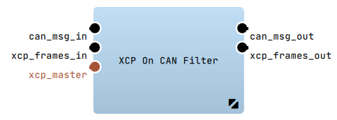
Introduction
The "XCP On CAN" - Filter can be used to communicate with ECUs that support XCP via CAN.
Configuration
To use it connect:
- the "xcp_frames_in" and "xcp_frames_out" Pins with the "XCP Master" - Filter.
- the "can_msg_in" and the "can_msg_out" Pins with your ECU
(e.g. with the "Vector CAN Device" - Receiver/Transmitter of the current ADTF Devicetoolbox)
Connected During Startup property to Connect if FilterGraph is Ready.
For further information about the configuration options please refer to XCP on CAN Filter Plugin.
Jump to topThe XCP on CAN FD Filter 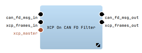
Introduction
The "XCP On CAN FD" - Filter can be used to communicate with ECUs that support XCP via CAN FD.
Configuration
To use it connect:
- the "xcp_frames_in" and "xcp_frames_out" Pins with the "XCP Master" - Filter.
- the "can_fd_msg_in" and the "can_fd_msg_out" Pins with your ECU
(e.g. with the "Vector CAN FD Device" - Receiver/Transmitter of the current ADTF Devicetoolbox)
Connected During Startup property to Connect if FilterGraph is Ready.
For further information about the configuration options please refer to XCP on CANFD Filter Plugin.
Jump to topThe XCP On FlexRay Filter 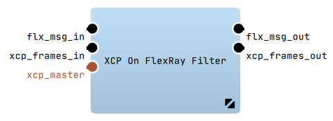
Introduction
The "XCP On FlexRay" - Filter can be used to communicate with ECUs that support XCP via FlexRay.
Configuration
To use it connect:
- the "xcp_frames_in" and the "xcp_frames_out" Pins with the "XCP Master" - Filter
- the "flx_msg_in" and the "flx_msg_out" Pins with your ECU
(e.g. with the "Vector FlexRay Device" - Receiver/Transmitter of the current ADTF Devicetoolbox)
Connected During Startup property to Connect if FilterGraph is Ready.
For further information about the configuration options please refer to XCP On FlexRay Filter Plugin.
Jump to topQt5 XCP Master GUI Filter (BETA)
Introduction
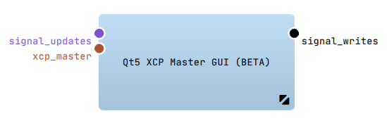 The "Qt5 XCP Master GUI" - Filter can be used to select XCP signals and parameters for reading and writing while runtime.
For further information about the configuration options please refer to Qt5 XCP Master GUI Filter Plugin (BETA) Plugin.
Configuration
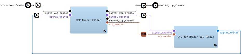
To use it connect:
- the "XCP Master" - Filter output pin "signal_updates" with the "Qt5 XCP Master GUI" - Filter input pin "signal_updates"
- the "Qt5 XCP Master GUI" - Filter output pin "signal_writes" with the "XCP Master" - Filter input pin "signal_writes"
- the "XCP Master" - Filter interface server pin "xcp_master" with the "Qt5 XCP Master GUI" - Filter interface client pin "xcp_master"
Overview
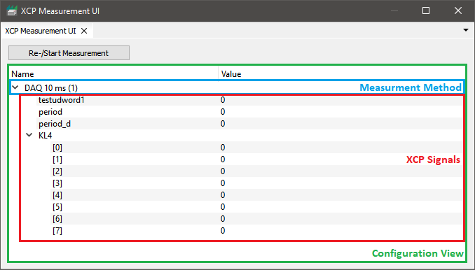
The "Qt5 XCP Master GUI" - Filter creates two xSystem Windows:XCP Measurement UI
Measurement Configuration.
This configuration consists of Measurement Methods (e.g. a DAQ - Event) which contain XCP Signals.
Regarding the configuration the signals will be requested from the ECU and decoded.
After pushing the Re-/Start Measurement - button, the signal values will be updated automatically and printed in the corresponding Value cell.
Measurement Configuration
-
Open the config menu of the measurement -
Configuration Viewand choose theAdd Measurement Method...- entry. -
This will open the
Measurement Method Dialog, where you can create aMeasurement Methodregarding your needs:
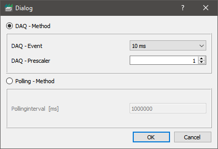
You can choose between- a DAQ - Method
- a Polling - Method
OK- button theMeasurement Methodwill appear in theConfiguration View. Due to the naming convention of theMeasurement Methods, you can easily identify the methods setting.
Examples:DAQ 10 ms (1): DAQ - Event10 mswith a prescaler1Polling 1000000 [ms]: Apolling intervalof1000000milliseconds
-
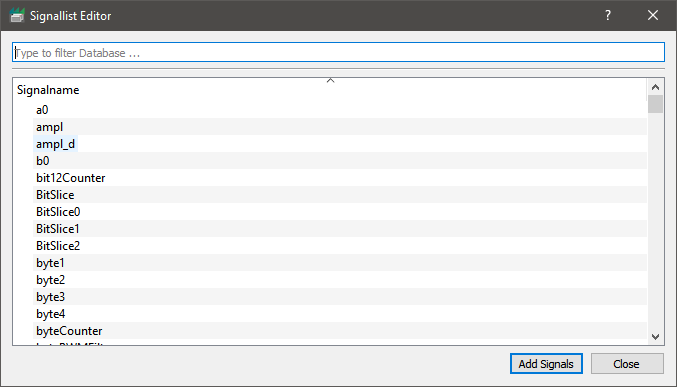
By opening the
Configuration Viewcontext menu on a selectedMeasurement Method, theAdd Signals to Measurement Method...- entry is activated. Pushing this will open theSignal List Editor- Dialog. -
Here you can select all signals, you like to add to the
Measurement Method
-
Since you finished your
Measurement Configuration, you're able to start the measurement by hitting theRe-/Start Measurement- button. The XCP Master Filter will request theXCP Signalsregarding theMeasurement Method. Signal updates will immediately be decoded and plotted.
Loading a Measurement Configuration
You can load a *.json measurement configuration by
- setting the filters
XCP Measurment UI - Configuration Fileproperty, to load the measurement file with filter intialisation - using the
Load Configuration File...ofConfiguration Viewcontext menu
*.json must declare for every measurment method:
- An unique
namefor the method - A measurement method
daq_eventorpolling_interval - A
signalsarray containing signal longnames
daq_prescaler
[
  {
    "daq_event": "10 ms",
    "name": "DAQ 10 ms (1)",
    "signals": [
      "BitSlice",
      "KL1"
    ]
  },
  {
      "name": "Polling 100000 [ms]",
      "polling_interval": 100000,
      "signals": [
          "bit12Counter"
      ]
  }
]
The Import Configuration from Mapfile... context menu entry will create the measurement configuration from a already existing *.map file.
You can find brief introduction of the *.map format here.
Saving a Measurement Configuration
Savewill override the current openend*.jsonfile.Saving measurement configs is only available for*.jsonfiles. Saving measurement configurations to*.mapfiles is not possible!Save As...will open the file dialog for saving the measurement configuration to a new*.jsonfile.
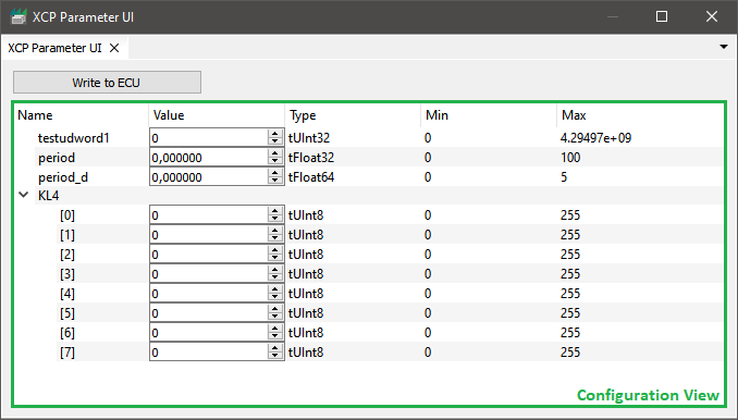
XCP Parameter UI
Parameter Configuration containing XCP Parameters.
For all configured elements, a SpinBox will be shown. With the help of these, you can change the value of the corresponding element.
Pushing the Write to ECU - button will transmit the updates to the ECU.
Parameter Configuration
-
Open the config menu of the parameter -
Configuration Viewand choose theAdd Parameters...- entry. -
The
Signal List Editor- Dialog will open, and you're able to add selected signals/parameters to theParameter Configuration. -
Use the SpinBoxes to change the parameters value and hit the
Write to ECU- button, to write all signal updates to the ECU.
Loading a Parameter Configuration
- setting the filters
XCP Parameter UI - Configuration Fileproperty, to load the parameter file with filter intialisation - the
Load Parameter File...context menu entry at runtime
- Vector
*.parfiles - Bosch
*.dcmfiles (VERSION > 2.x)Currently we are only supportingFESTWERTandFESTWERTEBLOCKparameter entries.
Saving a Parameter Configuration
Savewill override the current openend*.paror*.dcmfile.Save As...will open the file dialog for saving the parameter configuration to a new*.paror*.dcmfile.
Streaming services
XCP On Ethernet Receiver
Introduction
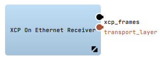 The "XCP On Ethernet Receiver" can be used to receive ethernet frames with XCP information and provide them to the XCP Master.
Configuration
To use it connect:
- the "xcp_frames" pin and a Sample Stream connected to a valid Streaming Inport (e.g. "si_xcpframes") of a Filter Graph
- the "transport_layer" output pin over a Bining Proxy to the XCP On Ethernet Transmitter "transport_layer" input pin
For further information about the configuration options please refer to XCP On Ethernet Receiver Plugin.
Jump to topXCP On Ethernet Transmitter
Introduction
![]() The "XCP On Ethernet Transmitter" can be used to send the XCP frames (from XCP Master Filter) via Ethernet to the ECU.
The "XCP On Ethernet Transmitter" can be used to send the XCP frames (from XCP Master Filter) via Ethernet to the ECU.
Configuration
To use it connect:
- the "xcp_frames" pin and a Sample Stream connected to the master_xcp_frames pin of the "XCP Master" - Filter.
- the "transport_layer" input pin over a Bining Proxy to the XCP On Ethernet Receiver "transport_layer" output pin
For further information about the configuration options please refer to XCP on Ethernet Transmitter Plugin.
Jump to top